Atlas · Plate IX · Clinical Services
Dental Radiography
Dental radiography covers how x-rays are produced, how they affect living tissue, how to keep doses low, and how to capture and read diagnostic images. For a hygienist it is daily work: choosing which images a patient needs, placing receptors with the paralleling or bisecting technique, spotting errors before deciding on a retake, and recognizing caries, calculus and bone loss on the finished image.
On the NBDHE, obtaining and interpreting radiographs is its own clinical services subarea, and patient cases show bitewings, periapicals and panoramic images to read. Expect questions on exposure factors, the inverse square law, error correction, normal landmarks and the ADA's 2024 change that dropped routine thyroid collars and lead aprons.
Blueprint Provision of Clinical Dental Hygiene Services · Obtaining and interpreting radiographs · 100 facts

In this plate, we cover
- 01 X-ray production 13 facts
- 02 Radiation biology 11 facts
- 03 Radiation protection 10 facts
- 04 Selection criteria 8 facts
- 05 Receptors and processing 9 facts
- 06 Intraoral technique 11 facts
- 07 Technique errors 8 facts
- 08 Panoramic imaging 9 facts
- 09 Normal radiographic anatomy 7 facts
- 10 Interpretation 11 facts
- 11 CBCT and emerging imaging 3 facts
01 · 13 facts
X-ray production
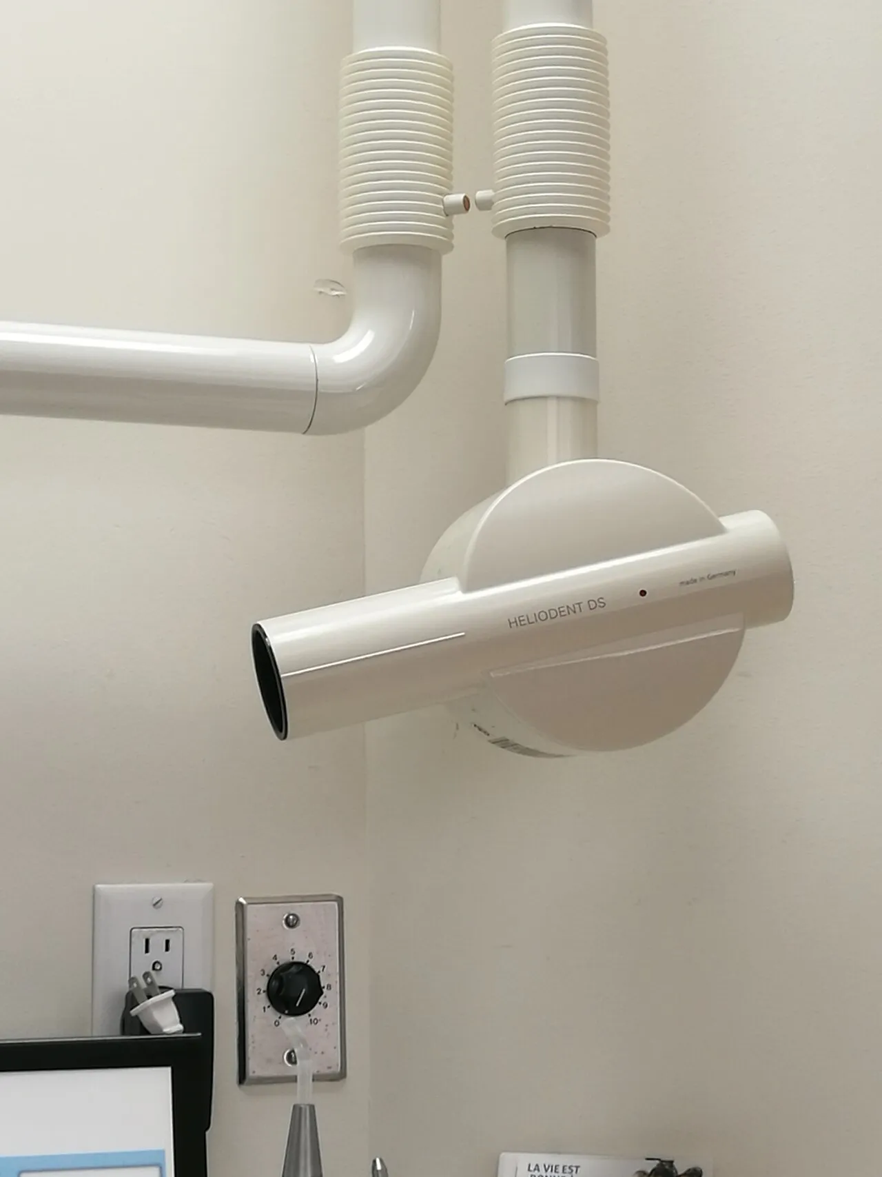
X-rays form when electrons from a heated tungsten filament strike a tungsten target; almost all of that energy becomes heat, and most of the useful beam is braking (bremsstrahlung) radiation. kVp sets penetration and contrast, while mA and exposure time set quantity and density. Filtration, collimation and the inverse square law shape what reaches the patient.
- X-rays form when electrons boiled off the heated tungsten filament (cathode, thermionic emission) strike the tungsten target (anode).T7
- Over 99% of the electron energy becomes heat; under 1% becomes x-rays. A copper stem carries heat away from the target.T7
- Most dental x-rays are bremsstrahlung ("braking") radiation; characteristic radiation is a small share.T7
- The molybdenum focusing cup aims the electron stream at the focal spot; a smaller focal spot gives a sharper image.T7

02 · 11 facts
Radiation biology
Most damage is indirect: ionized water forms free radicals that injure DNA. Fast-dividing, immature cells such as lymphocytes are the most sensitive. Stochastic effects like cancer have no threshold, while deterministic effects appear only above a threshold dose. Absorbed dose is measured in gray and effective dose in sievert.
- Most biologic damage is indirect: x-rays ionize water (radiolysis) and form free radicals that damage DNA.T7
- Law of Bergonie and Tribondeau: cells that divide quickly, are immature and less specialized are most radiosensitive.T7
- Most sensitive: lymphocytes, bone marrow, reproductive cells, intestinal epithelium. Least sensitive: mature bone, muscle and nerve cells.T7
- Stochastic effects (cancer, genetic mutations) have no threshold; probability rises with dose.T7S20
03 · 10 facts
Radiation protection
Dose is kept as low as diagnostically acceptable through selection criteria, the fastest receptor, rectangular collimation and careful technique that avoids retakes. Since 2024 the ADA no longer recommends routine thyroid collars or lead aprons, though some states still require them. Operators stand at least 6 feet away at 90-135 degrees or behind a barrier, and never hold the receptor.
- ALARA = as low as reasonably achievable; ALADA = as low as diagnostically acceptable.S20
- ADA 2024: thyroid collars and lead aprons are no longer recommended for routine intraoral, panoramic, cephalometric or CBCT imaging, including pregnant patients and children.S21S20
- The ADA's reasons: modern equipment and rectangular collimation deliver tiny doses, and shields can block the beam and cause retakes. Some states still require shields.S21
- Patient protection comes from selection criteria, fastest receptor (digital or F-speed film), rectangular collimation, good technique and avoiding retakes.S20S19
04 · 8 facts
Selection criteria
Images are prescribed after the clinical exam, based on each patient's needs rather than a calendar. A new adult usually gets bitewings plus a panoramic image or selected periapicals, with an FMX when disease is generalized. Recall bitewing intervals follow caries risk: every 6-18 months for high-risk adults and every 24-36 months for low-risk adults.
- Radiographs are prescribed after a clinical exam based on the patient's individual needs, not on a fixed schedule.S19
- New adult patient: usually posterior bitewings with a panoramic image or selected periapicals; an FMX for clinical evidence of generalized disease or extensive treatment history.S19
- Recall, adult with clinical caries or high caries risk: posterior bitewings every 6-18 months.S19
- Recall, adult with no caries and low risk: posterior bitewings every 24-36 months.S19
05 · 9 facts
Receptors and processing
Digital receptors are either direct sensors (CCD or CMOS) that show an image at once or phosphor plates (PSP) read by a laser scanner. Film still appears on the exam: developer turns exposed silver halide crystals black and fixer clears the unexposed ones. Processing faults have signature looks, from dark overdeveloped films to white fixer spots and fog.
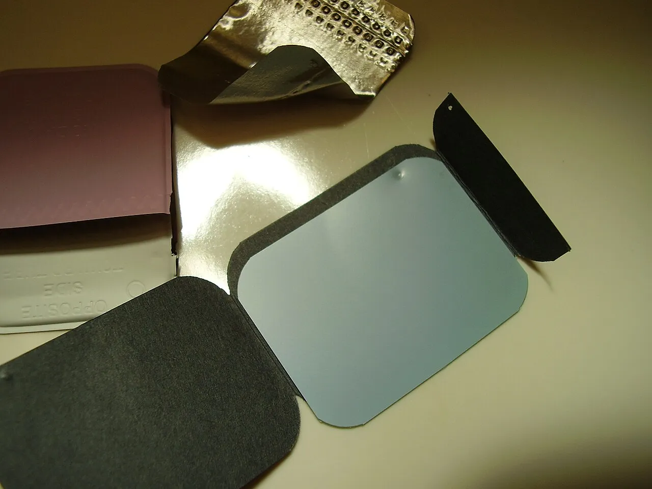
- Digital receptors: CCD and CMOS sensors (wired or wireless, direct, instant image) and PSP phosphor plates (indirect, scanned with a laser).T7
- PSP plates should be scanned soon after exposure; bent plates show creases and scratches; light exposure erases the image.T7
- A pixel is the digital equivalent of a silver halide crystal; image bit depth sets gray levels.T7
- Film emulsion contains silver halide crystals in gelatin; the embossed dot faces the tube (convex side toward the x-ray source).T7

06 · 11 facts
Intraoral technique
The paralleling technique places the receptor parallel to the tooth's long axis with the central ray perpendicular to both, giving the most accurate image. The bisecting technique aims at the line that bisects the tooth and receptor and distorts more. Bitewings use about +5 to +10 degrees of vertical angulation, and the buccal object rule (SLOB) locates objects buccolingually.
- Paralleling technique: receptor parallel to the long axis of the tooth, central ray perpendicular to both; uses a long (16 in) or 12 in PID and a holder. It gives the most accurate image.T7
- Bisecting angle technique: central ray perpendicular to the imaginary line bisecting the angle between the tooth's long axis and the receptor; more distortion.T7
- Bisecting vertical angles (approx.): maxillary incisors +40 to +50, canines +45 to +55, premolars +30 to +40, molars +20 to +30 degrees.T7
- Bisecting vertical angles (approx.): mandibular incisors -15 to -25, canines -20 to -30, premolars -10 to -15, molars -5 to 0 degrees.T7

07 · 8 facts
Technique errors
Each error has a cause you can correct. Too little vertical angulation elongates teeth, too much foreshortens them, and a horizontal angle that misses the contacts overlaps them. A PID not centered over the receptor leaves a clear cone cut. Movement blurs the image, a bent receptor stretches it, and a double exposure stacks two images.
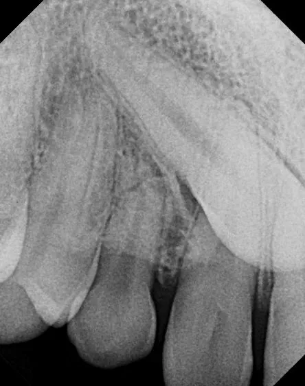
- Elongation: too little vertical angulation (bisecting) or receptor not parallel.T7
- Foreshortening: too much vertical angulation.T7
- Overlapped contacts: central ray not directed through the interproximal spaces (horizontal angulation error).T7
- Cone cut: clear (unexposed) curved or straight area because the PID was not centered over the receptor.T7
08 · 9 facts
Panoramic imaging
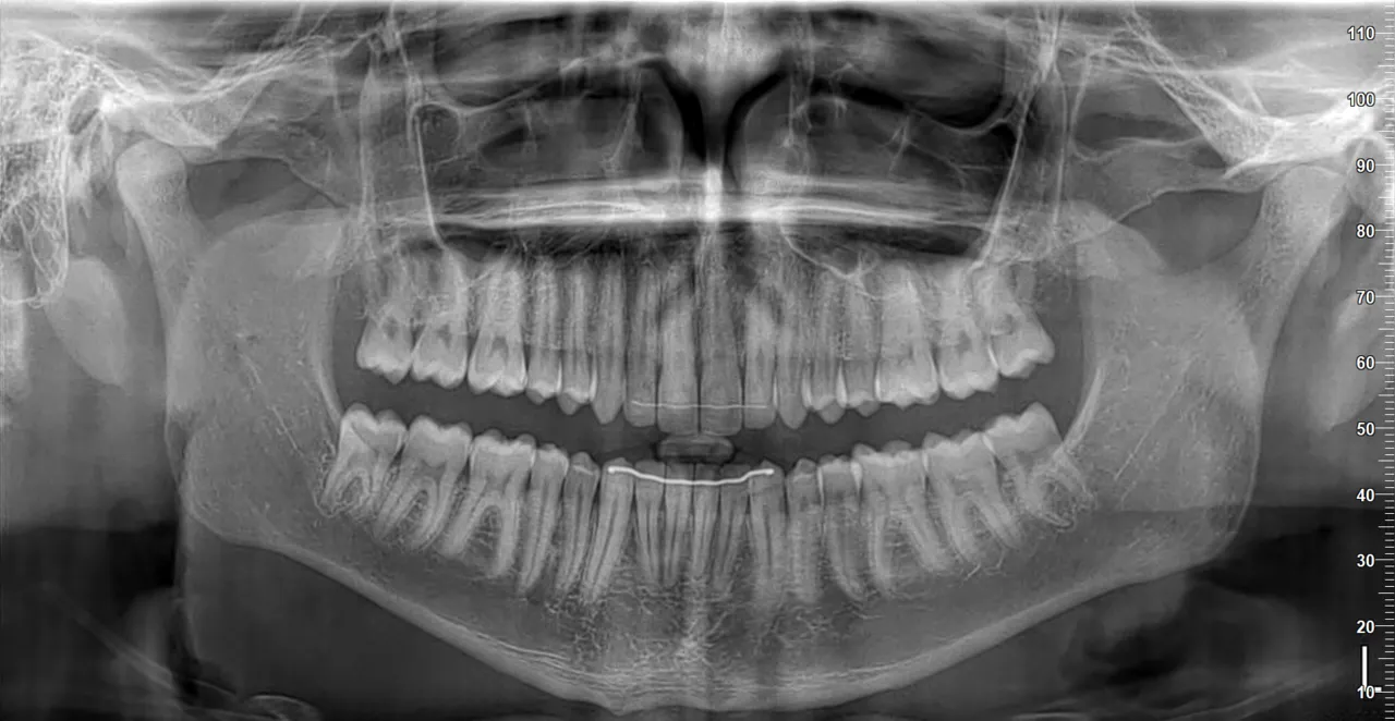
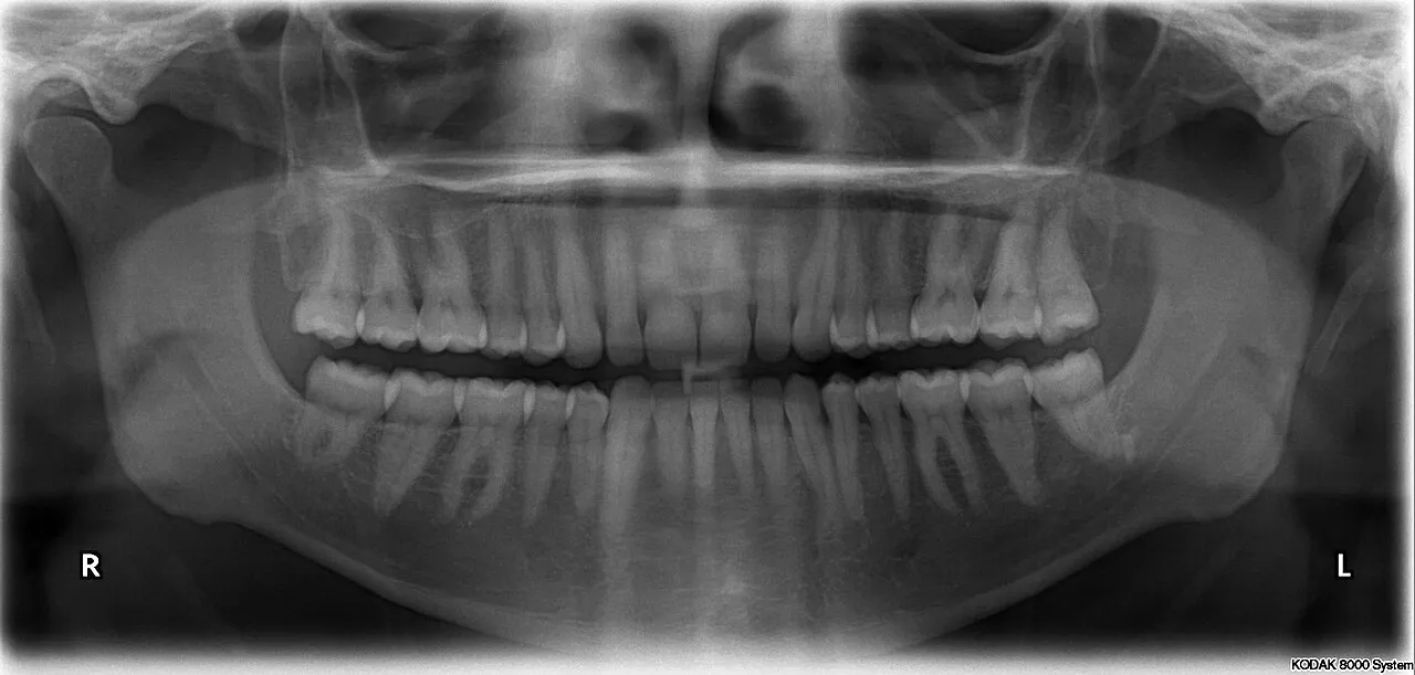
A panoramic unit sharpens only structures inside its focal trough. Correct positioning puts the Frankfort plane parallel to the floor, the midsagittal plane vertical, the incisors edge to edge in the bite block and the tongue on the palate. Positioning errors leave classic signs: a smile or frown occlusal plane, narrow or wide anteriors, or a spine shadow.
- The panoramic image uses a focal trough (image layer); structures outside it are blurred, magnified or narrowed.T7
- Positioning: Frankfort plane parallel to the floor, midsagittal plane perpendicular, teeth edge to edge in the bite block, tongue on the palate.T7
- Too far forward: narrow, blurred anterior teeth. Too far back: wide, blurred anterior teeth.T7
- Head turned or tilted: one side's teeth wider than the other and uneven rami.T7
09 · 7 facts
Normal radiographic anatomy
Radiolucent structures such as the pulp, PDL space, sinus and foramina appear dark; enamel, dentin, bone and metal appear light. Board items test landmarks by region: the incisive foramen and nasal fossa in the maxillary anterior, the sinus and zygomatic process in the posterior, and the genial tubercles, mental foramen and mandibular canal in the mandible.
- Radiolucent (dark): pulp, PDL space, sinus, nasal fossa, foramina, canals, air spaces. Radiopaque (light): enamel, dentin, bone, metal restorations.T7
- Maxillary anterior landmarks: incisive foramen (RL, between central roots), median palatine suture (RL line), nasal septum (RO), anterior nasal spine (RO V shape).T7
- Maxillary posterior landmarks: maxillary sinus (RL) and its septa, zygomatic process (RO "U" or "J"), maxillary tuberosity, hamulus, coronoid process of the mandible (RO triangle).T7
- The inverted "Y" is where the floor of the nasal cavity meets the anterior wall of the maxillary sinus, near the canine.T7

10 · 11 facts
Interpretation
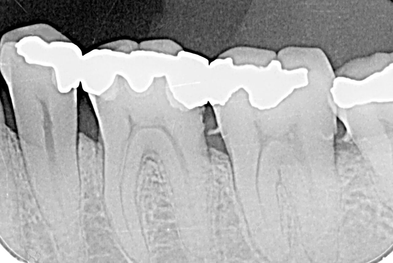
Bitewings are the best view for interproximal caries and crestal bone, though a lesion must lose about 40-50% of its mineral before it shows. Bone loss is horizontal or vertical relative to a line joining adjacent CEJs. Calculus spurs, overhangs and a widened PDL space are common findings, while cervical burnout and Mach bands only mimic disease.
- Bitewings are the best images for interproximal caries and crestal bone levels.T7S19
- About 40-50% demineralization is needed before a carious lesion shows radiographically, so radiographs underestimate depth.T7
- Radiographs cannot show buccal/lingual bone, early bone changes, soft tissue attachment or pocket depth; probing is still required.T7
- Horizontal bone loss runs parallel to a line joining adjacent CEJs; vertical (angular) bone loss runs oblique to it.T7

11 · 3 facts
CBCT and emerging imaging
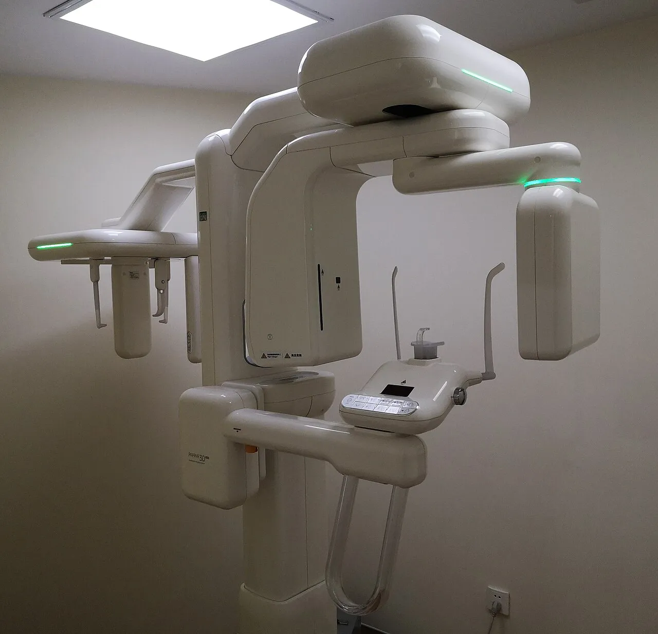
Cone beam CT produces 3D images for implant planning, impacted teeth, the TMJ and pathology, but it is not a screening tool and its dose varies widely with field of view. Intraoral cameras and scanners use no ionizing radiation. AI software that flags caries and bone loss supports, but does not replace, the clinician's diagnosis.
- CBCT gives 3D images used for implant planning, impacted teeth, TMJ and pathology; it is not for routine screening.S20
- Intraoral cameras and scanners do not use ionizing radiation.T7
- Artificial intelligence tools that flag caries and bone loss on radiographs are now FDA-cleared aids, not replacements for diagnosis. (verify for current listings)S20

Watch